Electronics > QUESTIONS & ANSWERS > EECS 31/CSE 31/ICS 151 Homework 5 Questions with Solutions (All)
EECS 31/CSE 31/ICS 151 Homework 5 Questions with Solutions
Document Content and Description Below
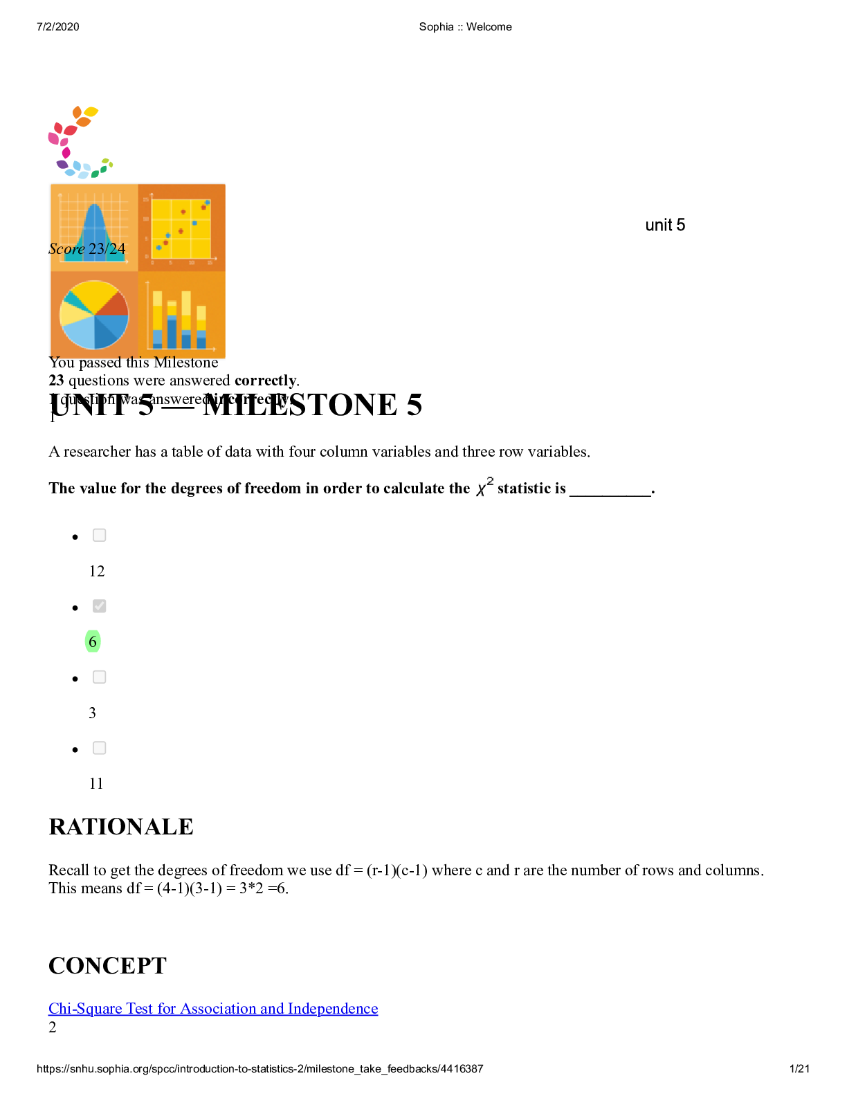
Problem 1 Question (SR latch) Draw the output and timing diagram of a (a) NOR and (b) NAND implementation of an SR latch for the input signals depicted in Figure P6.2. Figure P6.2 Figure P6.2 ... Problem 2 Question (SR latch) Derive an implementation of a clocked SR latch using only: NOR gates NAND gates AND, OR and INVERT gates Problem 3 Question (JK flip-flops) Derive the output waveforms of a master-slave JK flip-flop for the input waveforms depicted in Figure P6.6. Figure P6.6 Figure P6.6 Problem 4 Question (Sequential Analysis) Derive a (a) state table and (b) state diagram for the sequential circuit shown in Figure P6.9 Figure P6.9 Figure P6.9 Problem 5 Question (State minimization) Derive the minimal-state FSM from the state/output table shown in Figure P6.12. PRESENT STATE NEXT STATE x = 0 x = 1 S0 S0/1 S4/0 S1 S0/0 S4/0 S2 S1/0 S5/0 S3 S1/0 S5/0 S4 S2/0 S6/1 S5 S2/0 S6/1 S6 S3/0 S7/1 S7 S3/0 S7/1 Figure P6.12 Problem 6 Question (Sequential Synthesis) Design a counter that counts in the sequence 0, 1, 2, 3, 4, 5, 6, 7, 8, 9, 0,..., using natural binary encoding and D-type flip-flops. Problem 7 Question (Sequential Synthesis) Design a recognizer that recognizes an input sequence that has at least three 1's. The recognizer has a single input X, and a single output Y, in addition to an asynchronous Reset signal. The recognizer sets the output Y to 1 if the input signal X was equal to 1 in at least 3 clock cycles after the Reset was disasserted. For the above recognizer described above: Devise the state diagram. Minimize the number of states. Encode the states to minimize the combinatorial logic. Draw a schematic diagram using D flip-flops. Problem 8 Question Sequential Synthesis) Design a simplified traffic-light controller that switches traffic lights on a crossing where a north-south (NS) street intersects an east-west (EW) street. The input to the controller is the WALK button pushed by pedestrians who want to cross the street. The outputs are two signals NS and EW that control the traffic lights in NS and EW directions. When NS or EW are 0, the red light is on and when they are 1, the green light is on. When there are no pedestrians, NS=0 and EW=1 for 1 minute, followed by NS=1 and EW=0 for 1 minute and so on. When a WALK button is pushed, NS and EW both come 1 for a minute when the present minute expires. After that the NS and EW signals continue alternating. For the traffic-light controller: Develop a state diagram and state/output table. Minimize the number of states. Encode the states. Draw a schematic diagram. [Show More]
Last updated: 1 year ago
Preview 1 out of 5 pages

Buy this document to get the full access instantly
Instant Download Access after purchase
Add to cartInstant download
We Accept:

Reviews( 0 )
$15.50
Document information
Connected school, study & course
About the document
Uploaded On
Sep 08, 2020
Number of pages
5
Written in

Additional information
This document has been written for:
Uploaded
Sep 08, 2020
Downloads
0
Views
111
.png)


.png)