Information Technology > Lab Experiment > LAB 3 Objective.pdf (All)
LAB 3 Objective.pdf
Document Content and Description Below
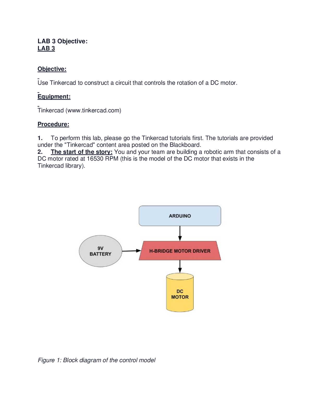
LAB 3 Objective: LAB 3 Objective: Use Tinkercad to construct a circuit that controls the rotation of a DC motor. Equipment: Tinkercad (www.tinkercad.com) Procedure: 1. To perform this lab, plea... se go the Tinkercad tutorials first. The tutorials are provided under the "Tinkercad" content area posted on the Blackboard. 2. The start of the story: You and your team are building a robotic arm that consists of a DC motor rated at 16530 RPM (this is the model of the DC motor that exists in the Tinkercad library). Figure 1: Block diagram of the control model3. Create a new Tinkercad project in your provided account, and title it "Lab 3 - DC Control" 4. Build a circuit based on the block diagram shown in Fig. 1. This is the Tinkercad model of the situation presented in step 2. Here is more information on what an H-Bridge motor controller is: https://blog.digilentinc.com/what-is-an-h-bridge/. 5. Write a general code for the Arduino Uno R3 to run the DC motor at any desired RPM (speed). This means that: a. The Arduino takes an integer input from the Serial Monitor and converts it to its corresponding PWM (Pulse-Width Modulation) number using the "map()" function. b. It then sends this PWM number to the DC motor using the "analogWrite()" command through the H-Bridge driver. Question 1: What do you think is the maximum PWM value? Why? Please explain in detail. c. The result is that the DC motor rotates at an RPM of approximately the input integer (the RPM is shown on the rotating motor). The input integer and the PWM number sent to the H-Bridge should be displayed in the Serial Monitor LAB 5 Objective: Use Tinkercad to advance the control of DC Motors using sensors. Equipment: Tinkercad (www.tinkercad.com) Procedure: ~Part I~ 1. Duplicate your Tinkercad project from Lab 3 and rename the duplicate to "Lab 5: Drill". This part will be done here. 2. The story comes to a halt: You and your team conclude that this motor rotates at very high RPM values, and therefore it may not be a good fit for a robotic arm; especially that the motion of the motor is continuous. Thus, you decide to use what you have built for another application: an automatic industrial drill. 3. Revise your circuit based on the block diagram shown in Figure 1. [Show More]
Last updated: 1 year ago
Preview 1 out of 13 pages
Reviews( 0 )
Document information
Connected school, study & course
About the document
Uploaded On
Jul 28, 2022
Number of pages
13
Written in

Additional information
This document has been written for:
Uploaded
Jul 28, 2022
Downloads
0
Views
83


.png)