Electrical Engineering > Lab Report > EE 118 lab report - San Jose State University EE MISC (All)
EE 118 lab report - San Jose State University EE MISC
Document Content and Description Below
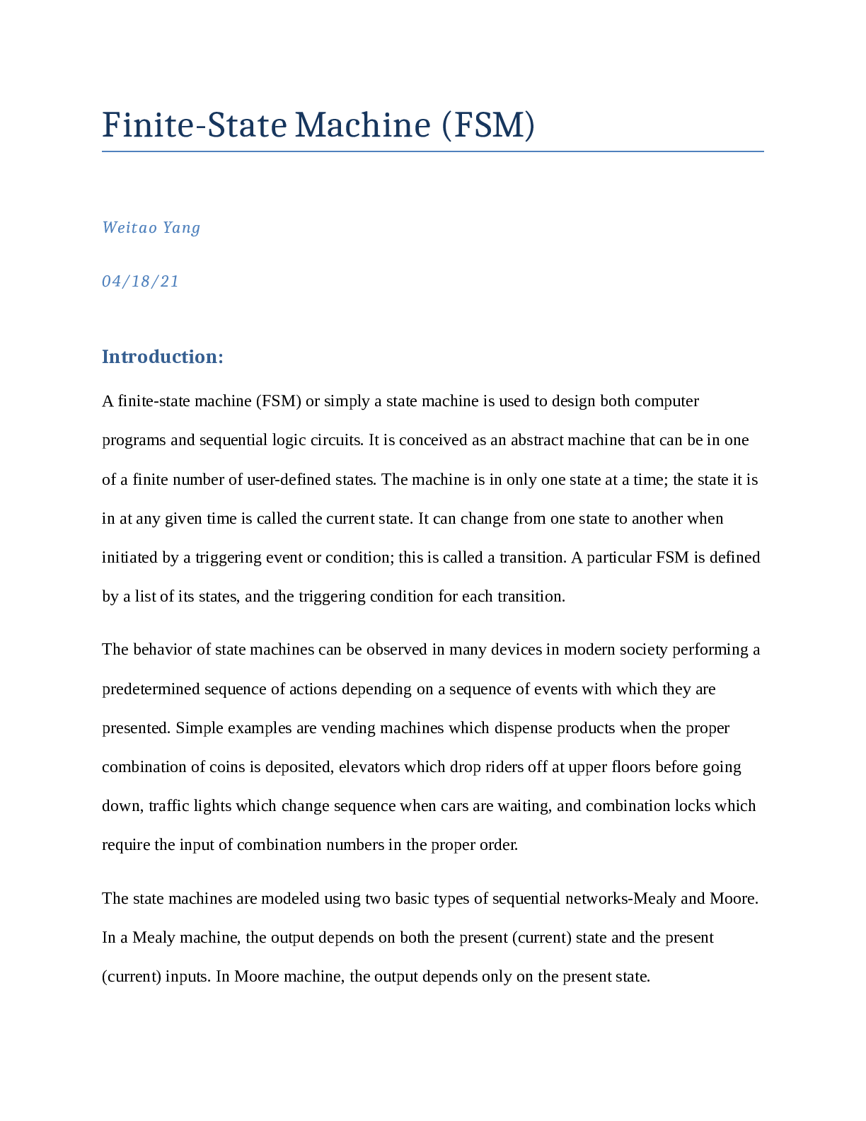
Finite-State Machine (FSM) Weitao Yang 04/18/21 Introduction: A finite-state machine (FSM) or simply a state machine is used to design both computer programs and sequential logic circuits. It is ... conceived as an abstract machine that can be in one of a finite number of user-defined states. The machine is in only one state at a time; the state it is in at any given time is called the current state. It can change from one state to another when initiated by a triggering event or condition; this is called a transition. A particular FSM is defined by a list of its states, and the triggering condition for each transition. The behavior of state machines can be observed in many devices in modern society performing a predetermined sequence of actions depending on a sequence of events with which they are presented. Simple examples are vending machines which dispense products when the proper combination of coins is deposited, elevators which drop riders off at upper floors before going down, traffic lights which change sequence when cars are waiting, and combination locks which require the input of combination numbers in the proper order. The state machines are modeled using two basic types of sequential networks-Mealy and Moore. In a Mealy machine, the output depends on both the present (current) state and the present (current) inputs. In Moore machine, the output depends only on the present state. In this lab, we will further analyze two simplest sequential networks with both Mealy and Moore FSM, interpret the given Verilog codes, simulate the waveforms through Vivado, and demonstrate the same results on FPGA board. Theory of Operation and explanation of the design: Mealy FSM: A general model of a Mealy sequential machine consists of a combinatorial network, which generates the outputs and the next state, and a state register which holds the present state as shown below. Figure 1. Mealy Finite-State Machine Schematic According to figure 1, outputs are from the Next State and Output Logic, and either inputs or register(clock and reset) can directly affect the values of outputs. Based on the theorem, the Verilog code to design the target Parity Checker (Mealy state diagram shown as figure 2) is given and listed on figure 3. Figure 2. Mealy State Diagram for Parity Checker In the state diagram, there are some labeled digital numbers as “rx/z”: r refers to reset input, x is the input, and z refers to the output. S0 and S1 refer to the state. In this case, S0 equals to 0, and S1 equals to 1. According to the diagram, reset input makes the state turn back to S0, and x input makes the state transition. [Show More]
Last updated: 1 year ago
Preview 1 out of 18 pages
Reviews( 0 )
Document information
Connected school, study & course
About the document
Uploaded On
Dec 22, 2022
Number of pages
18
Written in

Additional information
This document has been written for:
Uploaded
Dec 22, 2022
Downloads
0
Views
67


 (1).png)


.png)

.png)

.png)