Electronics > Lab Experiment > University of Illinois, Urbana Champaign ECE 210 : Lab 4 Solutions (Fourier transform and AM radio) (All)
University of Illinois, Urbana Champaign ECE 210 : Lab 4 Solutions (Fourier transform and AM radio)
Document Content and Description Below
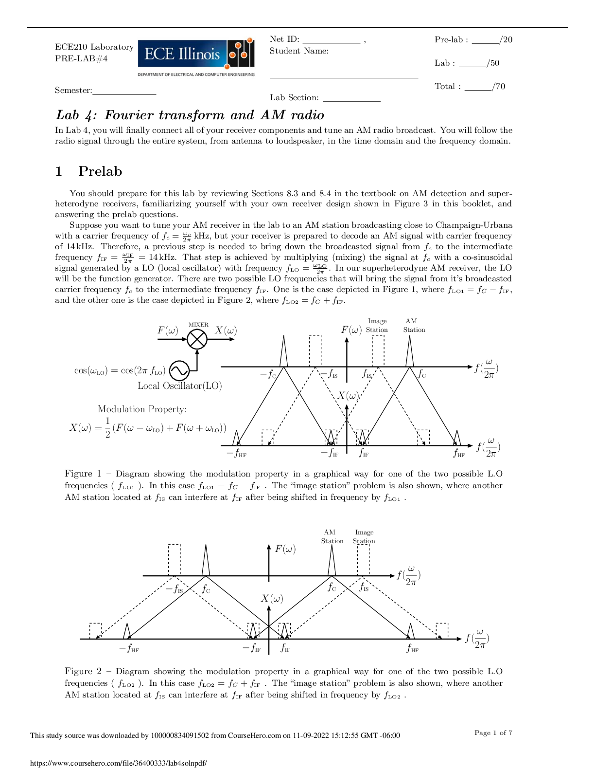
ECE210 Laboratory PRE-LAB#4 Semester: Net ID: , Student Name: Lab Section: Pre-lab : /20 Lab : /50 Total : /70 Lab 4: Fourier transform and AM radio In Lab 4, you will finally connect all of... your receiver components and tune an AM radio broadcast. You will follow the radio signal through the entire system, from antenna to loudspeaker, in the time domain and the frequency domain. 1 Prelab You should prepare for this lab by reviewing Sections 8.3 and 8.4 in the textbook on AM detection and superheterodyne receivers, familiarizing yourself with your own receiver design shown in Figure 3 in this booklet, and answering the prelab questions. Suppose you want to tune your AM receiver in the lab to an AM station broadcasting close to Champaign-Urbana with a carrier frequency of fc = !c 2⇡ kHz, but your receiver is prepared to decode an AM signal with carrier frequency of 14 kHz. Therefore, a previous step is needed to bring down the broadcasted signal from fc to the intermediate frequency fIF = !IF 2⇡ = 14 kHz. That step is achieved by multiplying (mixing) the signal at fc with a co-sinusoidal signal generated by a LO (local oscillator) with frequency fLO = !LO 2⇡ . In our superheterodyne AM receiver, the LO will be the function generator. There are two possible LO frequencies that will bring the signal from it’s broadcasted carrier frequency fc to the intermediate frequency fIF. One is the case depicted in Figure 1, where fLO1 = fC fIF, and the other one is the case depicted in Figure 2, where fLO2 = fC + fIF. f( ! 2⇡ ) fIF fIS F(!) X(!) F(!) X(!) cos(!LO) = cos(2⇡ fLO) fIF fC fIS fC fHF fHF f( ! 2⇡ ) MIXER Image Station AM Station X(!) = 1 2 (F(! !LO) + F(! + !LO)) Modulation Property: Local Oscillator(LO) Figure 1 – Diagram showing the modulation property in a graphical way for one of the two possible L.O frequencies ( fLO1 ). In this case fLO1 = fC fIF . The “image station” problem is also shown, where another AM station located at fIS can interfere at fIF after being shifted in frequency by fLO1 . F(!) Image Station AM Station f fC fIS IS fC X(!) f( ! 2⇡ ) f( ! 2⇡ ) fHF fIF fIF fHF Figure 2 – Diagram showing the modulation property in a graphical way for one of the two possible L.O frequencies ( fLO2 ). In this case fLO2 = fC + fIF . The “image station” problem is also shown, where another AM station located at fIS can interfere at fIF after being shifted in frequency by fLO2 . [Show More]
Last updated: 1 year ago
Preview 1 out of 7 pages
Reviews( 0 )
Document information
Connected school, study & course
About the document
Uploaded On
Nov 10, 2022
Number of pages
7
Written in

Additional information
This document has been written for:
Uploaded
Nov 10, 2022
Downloads
0
Views
48


.png)