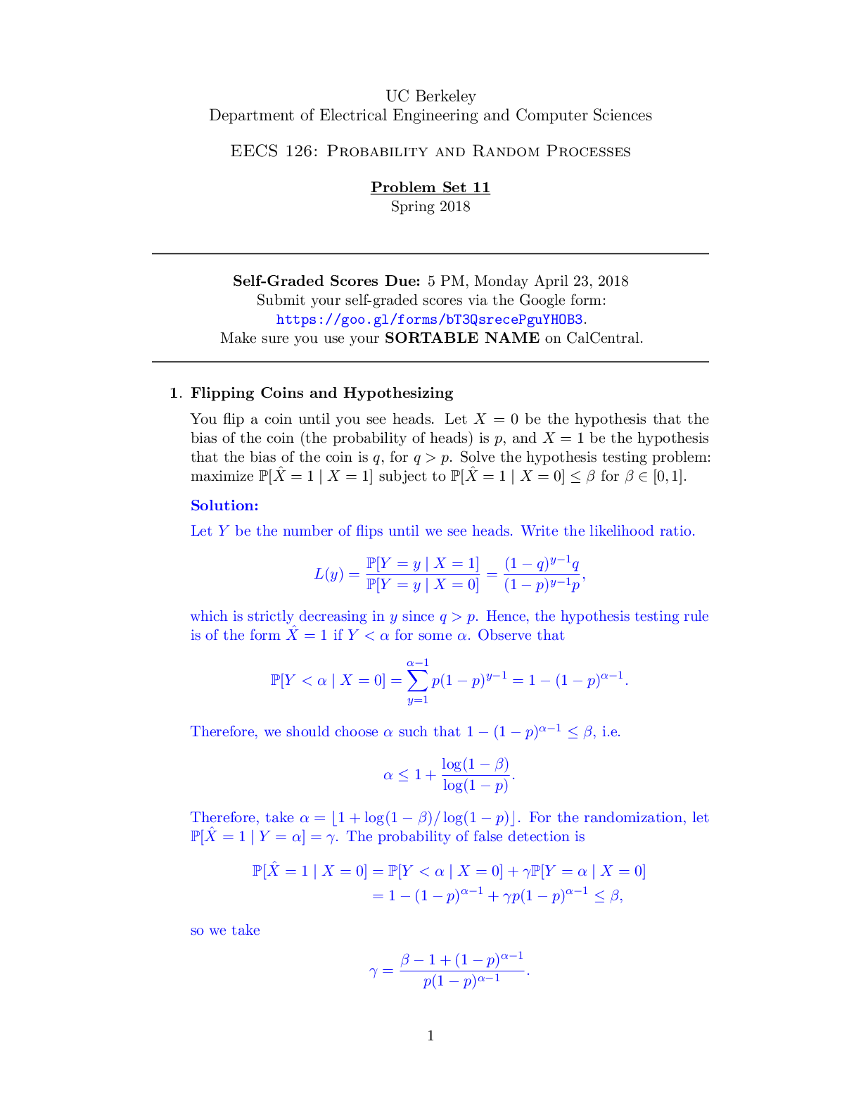
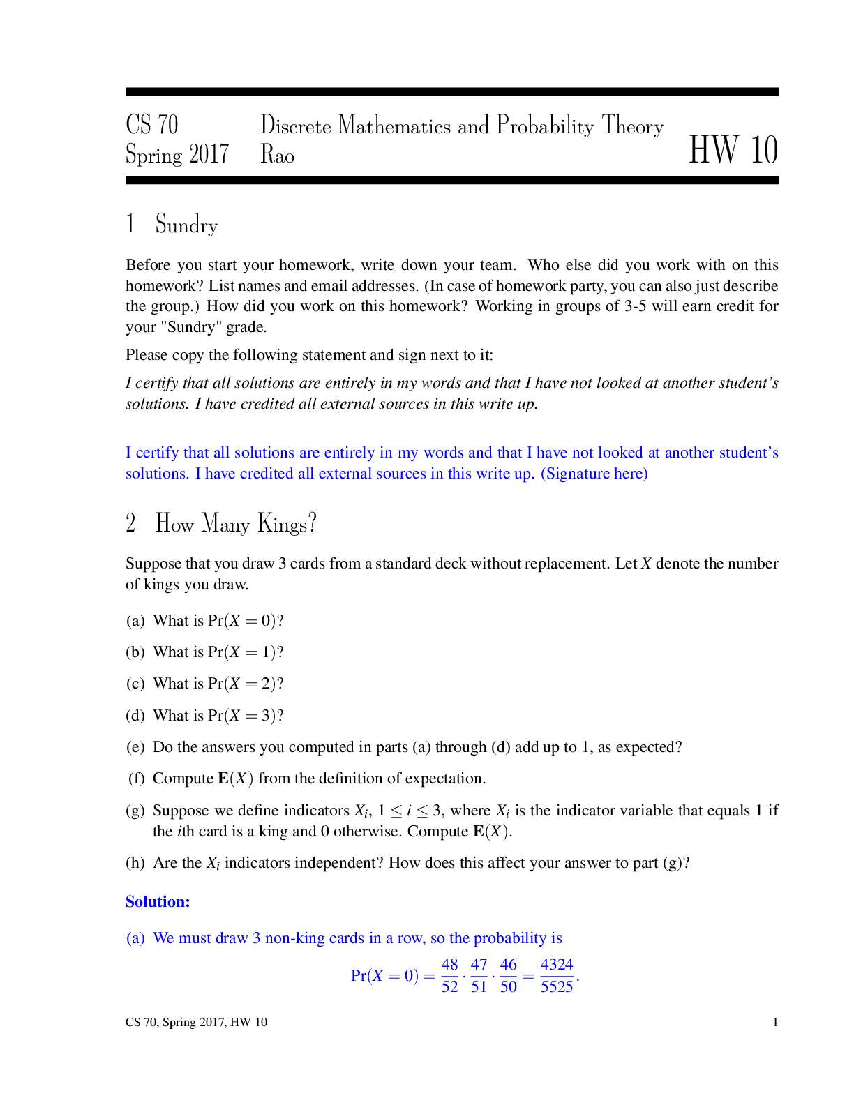
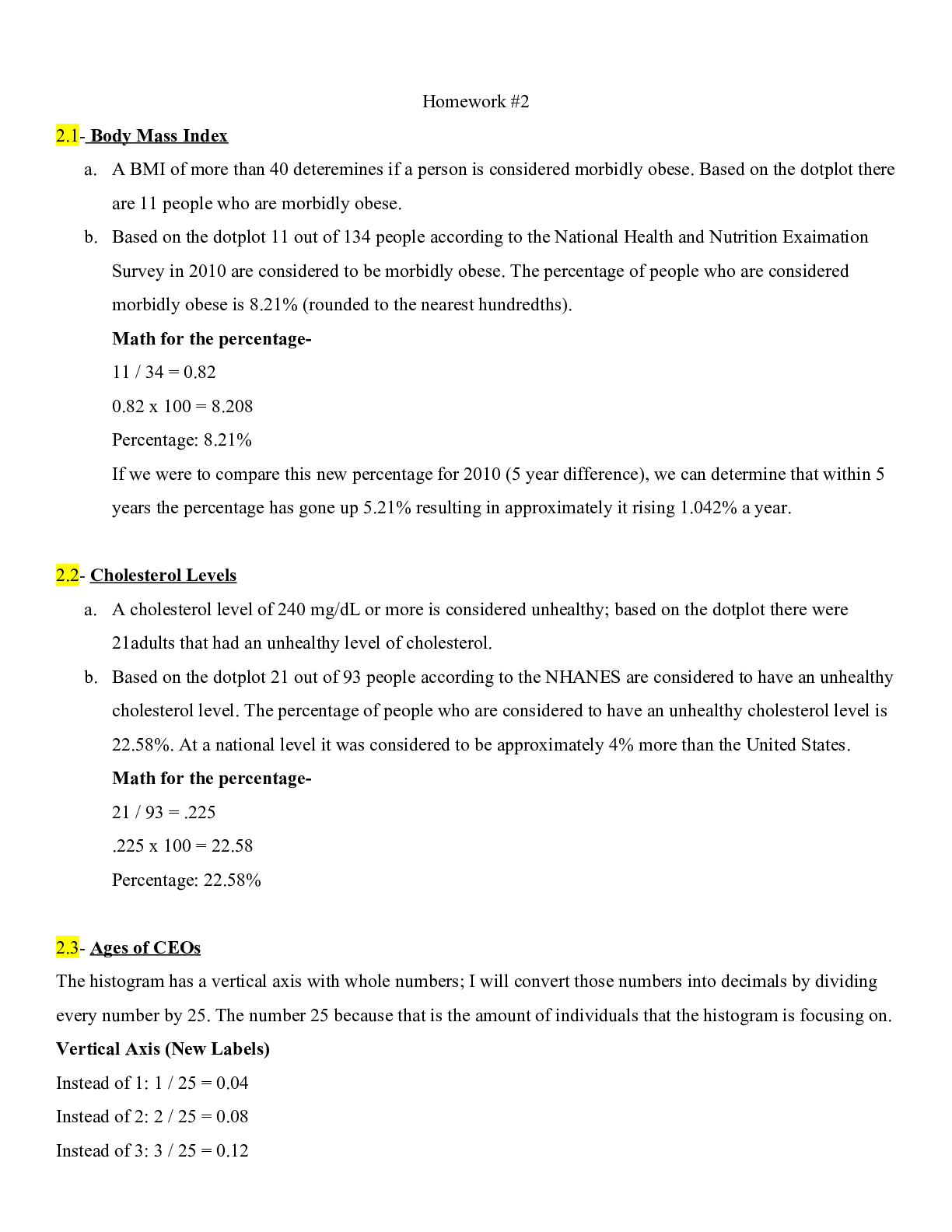
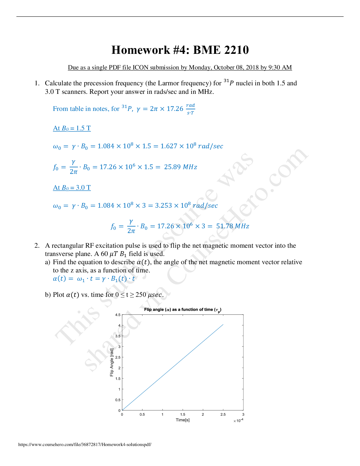
Medical Studies > QUESTIONS & ANSWERS > Questions and Answers > University of Iowa - BME 2210 Homework3_solutions. (All)
Questions and Answers > University of Iowa - BME 2210 Homework3_solutions.
Document Content and Description Below
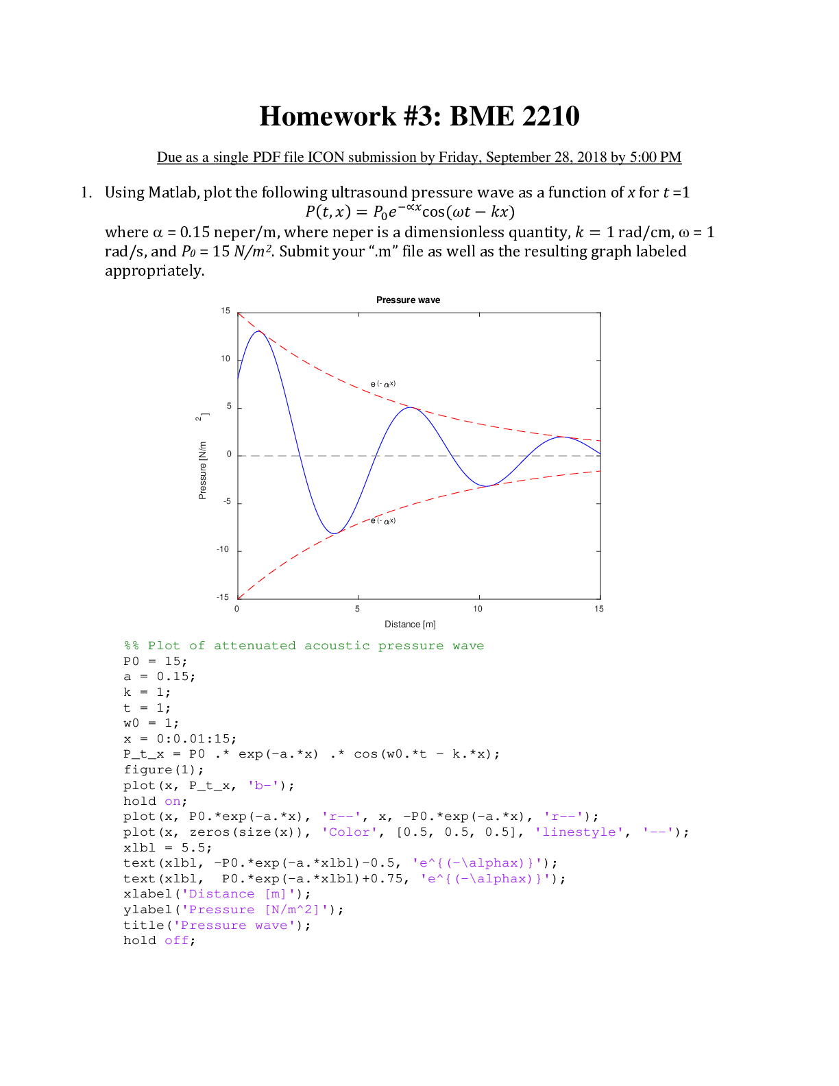
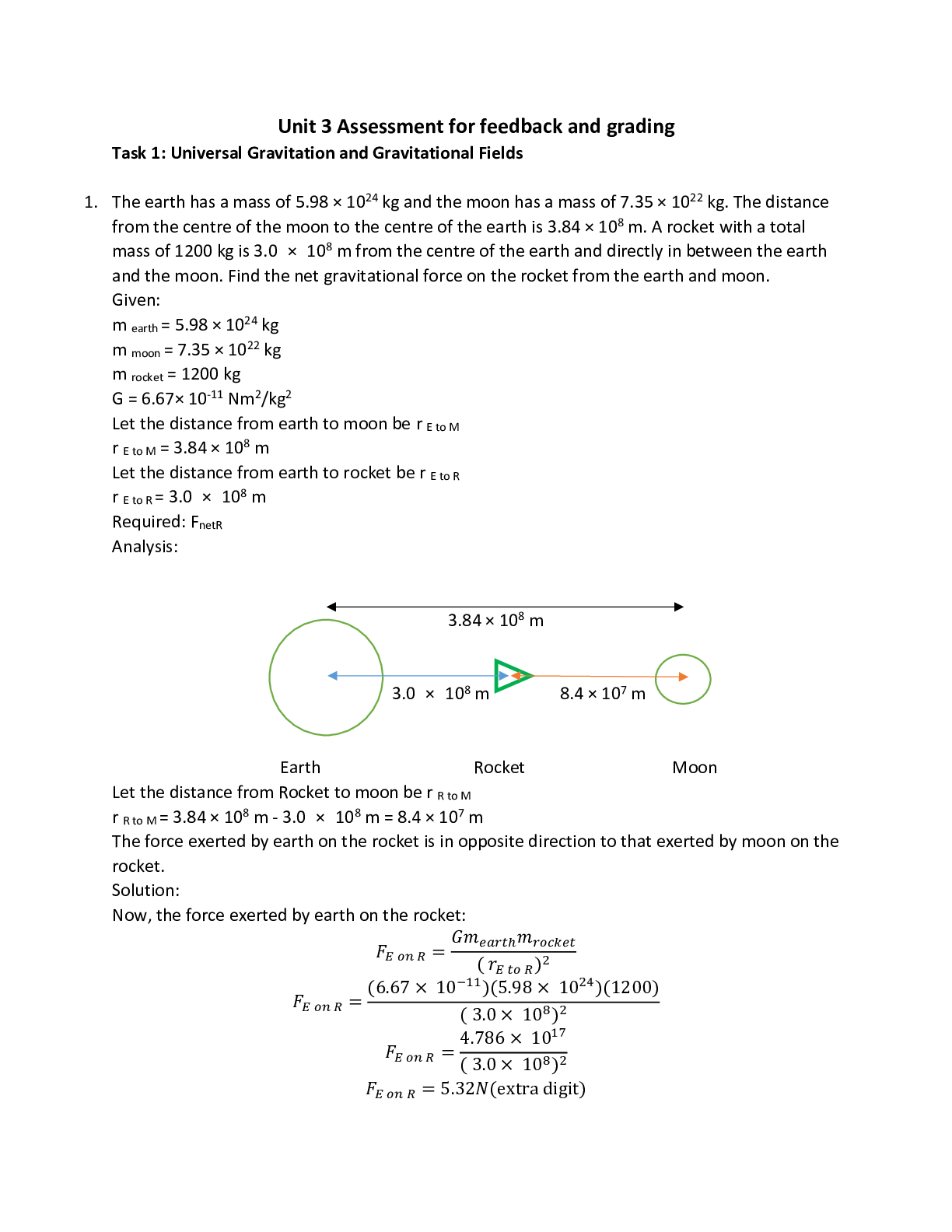
Homework 3: BME 2210 Due as a single PDF file ICON submission by F 1. Using Matlab, plot the following ultrasound pressure wave as a function where 5 neper/m, where neper is a dimensionless q... uantity, rad/s, and Submit your “.m” file as well as the resulting graph labeled appropriately. Plot of attenuated acoustic pressure wave 2. An ultrasound imaging system is used to create a B-mode image of a soft-tissue sample. We want an image that extends to a depth of 30 cm from the transducer. Assume that 175 A-mode lines are used to create the B-mode image. a) How much time is required to acquire the data for each A-mode line? b) What is the maximum possible B-mode image refresh rate, in frames per second? c) Using the same refresh rate calculated above, what is the maximum depth possible if all A-mode lines are acquired simultaneously? 3. Answer the following showing your work: a) If the attenuation coefficient of the heart muscle ??ℎ?? = 0.185 (???? ∙ ??????)-1, calculate the distance at which the signal amplitude of a 2-MHz ultrasound beam will be reduced by half traveling through heart muscle. b) You have two transducers available, a 25-MHz transducer and a 3-MHz transducer. Which transducer should you use to perform an echocardiogram, and why (show your work)? 4. An ultrasound beam incident at an angle of 15° from fat tissue into muscle tissue, calculate the angle of refraction using the table below? 5. Using the table above and in the figure shown below, the transducer is stimulated with a A B Fat Transducer short pulse resulting in a short burst of pressure traveling through the sequence of materials shown in figure. Assume that no echoes are returned at the transducer-tissue interface. The transducer is operating at 3 MHz frequency, measured from the transducer edge, A = 3 cm and B = 5 cm. Use specific sound speeds in the corresponding materials. a) Assuming perpendicular incidence and that the system is setup to equalize the amplitude of all the returned signals (don’t account for attenuation and reflection/transmittance at interfaces), sketch the timing of the first echoes (signals) received by the transducer from interfaces A, and B. b) Now accounting for attenuation and reflection/transmittance at interfaces calculate the actual amplitudes of the pulses from interfaces A and B relative to the incident amplitude. end [Show More]
Last updated: 1 year ago
Preview 1 out of 5 pages
Reviews( 0 )
Document information
Connected school, study & course
About the document
Uploaded On
Feb 19, 2021
Number of pages
5
Written in

Additional information
This document has been written for:
Uploaded
Feb 19, 2021
Downloads
0
Views
55


.png)


 Problem Set 4.png)