Thermodynamics > Lab Report > Advanced Thermofluids University of New South WalesMMAN 36103610 REPORT (All)
Advanced Thermofluids University of New South WalesMMAN 36103610 REPORT
Document Content and Description Below
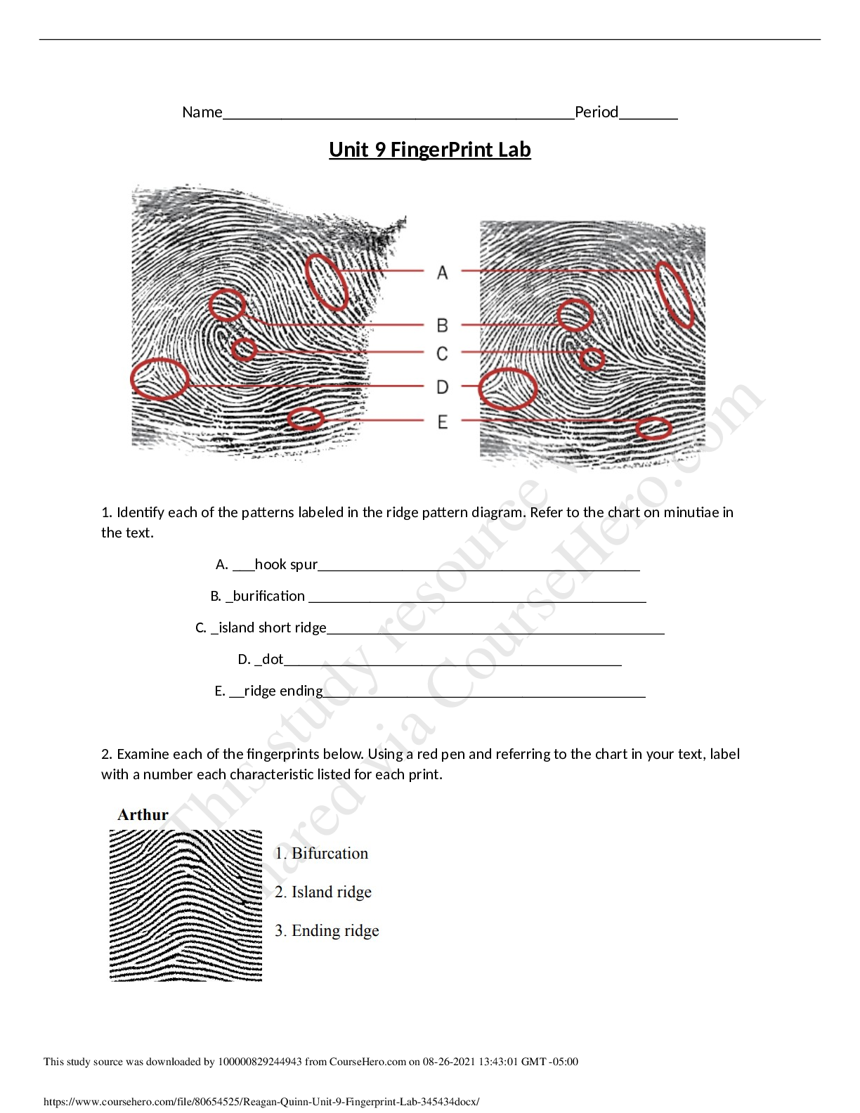
University of New South Wales MMAN 3610 Advanced Thermofluids Final Lab Report Author: Jason Phan, z5114778 Lecturer: Phil Howlin September 25, 2018Contents 1 Laboratory H1 . . . . . . . . . ... . . . . . . . . . . . . . . . . . . . . . . . . . . . . . . 2 1.1 Results . . . . . . . . . . . . . . . . . . . . . . . . . . . . . . . . . . . . . . . 2 1.2 Discussion and Conclusion . . . . . . . . . . . . . . . . . . . . . . . . . . . . . 4 2 Laboratory H2 . . . . . . . . . . . . . . . . . . . . . . . . . . . . . . . . . . . . . . . 5 2.1 Results . . . . . . . . . . . . . . . . . . . . . . . . . . . . . . . . . . . . . . . 5 2.2 Discussion and Conclusion . . . . . . . . . . . . . . . . . . . . . . . . . . . . . 7 1MMAN 3610: Lab Report z5114778 1 Laboratory H1 1.1 Results Laboratory H1 explores 4 different types of heat exchangers with two types of flow, counter flow and parallel flow and two different structure, shell and tube and concentric. The method and calculation used for this study can be found in the "Heat Exchanger Experiment (H1)" on Moodle [1]. Due to significant variation of the results obtained by the cohort, the results derived from the data is not reliable nor valid. However, meaningful discussions can be drawn out from these invalid results. Obvious outliers were removed for the analysis. The following figures are the results from experiment H1. (a) Heat transfer coefficient vs flow rate (b) Mean temperature efficiency vs flow rate Figure 1: Results in respect to cold flow rates. Figure 2: Qh vs ∆T1 for all heat exchangers. Qh is heat loss from hot water. 2MMAN 3610: Lab Report z5114778 Figure 3: Qc vs ∆T1 for all heat exchangers. Qc is heat gained by cold water. Theoretically, counterflow heat exchangers are more efficient than parallel flow due to a more uniform temperature difference over the entire length of the fluid’s path between the fluids. Therefore, is it safe to assume that the counterflow shell and tube will be the most efficient and parallel concentric being the least efficient. However, analysing the results obtained through the cohort’s data, Figure 1a, Figure 1b and Figure 2 & 3 does not demonstrate the theoretical concept. Looking at Figure 1a, the heat transfer coefficient are all increasing at a decreasing rate. This result emulates a real life situation as an increase in flow rate will increase the heat transfer coefficient and hence increasing the efficiency of the heat exchanger. However, this graph shows parallel shell and tube and counter flow shell and tube having the best heat transfer coefficient while counterflow concentric heat exchanger having the worse. This is clearly wrong since counter flow heat exchangers are known to be more efficient than parallel flow and hence it must have a greater heat transfer coefficient for increasing flow rates. Therefore, this result is deemed to be invalid and reasons for these major discrepancies will be discussed at the end of this section. In addition, observing Figure 1b, all 4 curves have similar trends, decreasing at a decreasing rate. It is clear that the data inventory is poor as the curves are intersecting each other. However, the trend seems reasonable as lower flow rates allows heat to be exchanged more easily. Therefore, in real life applications, a compromise of the flow rate must be taken into account as it cannot be too slow since heat transfer coefficient increases with flow rate and it cannot be too fast since the mean temperature efficiency decreases with increasing flow rate. Thus, a compromise of the flow rate is chosen to optimise both traits. The results obtained shows that parallel concentric heat exchanger is overall the most efficient and the counter flow concentric being the least. Again, the result is deemed to be invalid as the counterflow shell and tube must be the most efficient and the parallel concentric being the least efficient. Figure 2 & 3 produced the most meaningful results compared to the previous two graphs. We can see that for both counterflow heat changers, the trend is roughly linear. Therefore, we can assume that this is the same for the parallel flow. For both figures, both counter flow heat exchangers are above the parallel flow exchangers. This is true since counter flow is more efficient and hence more heat is loss from hot water and gained by cold water. This experiment is not adiabatic so there will be some heat loss or gained by the surroundings. From this we can see that the counterflow exchangers are more efficient than the parallel flow. However, this curve is contradictory because for counter flow, the shell and tube is more efficient but for parallel, it’s the concentric heat exchanger 3MMAN 3610: Lab Report z5114778 that’s more efficient. Therefore, this result is also deemed to be invalid as it does not correlate with the theoretical result. [Show More]
Last updated: 1 year ago
Preview 1 out of 10 pages

Reviews( 0 )
Document information
Connected school, study & course
About the document
Uploaded On
Jul 13, 2021
Number of pages
10
Written in

Additional information
This document has been written for:
Uploaded
Jul 13, 2021
Downloads
0
Views
64


 (1).png)
.png)

.png)