Engineering > Lab Experiment > Lab Experiment > PLC Timer and Counter_MODULE NO. 6 _ Mapúa Institute of Technology ECEA 103L (All)
Lab Experiment > PLC Timer and Counter_MODULE NO. 6 _ Mapúa Institute of Technology ECEA 103L
Document Content and Description Below
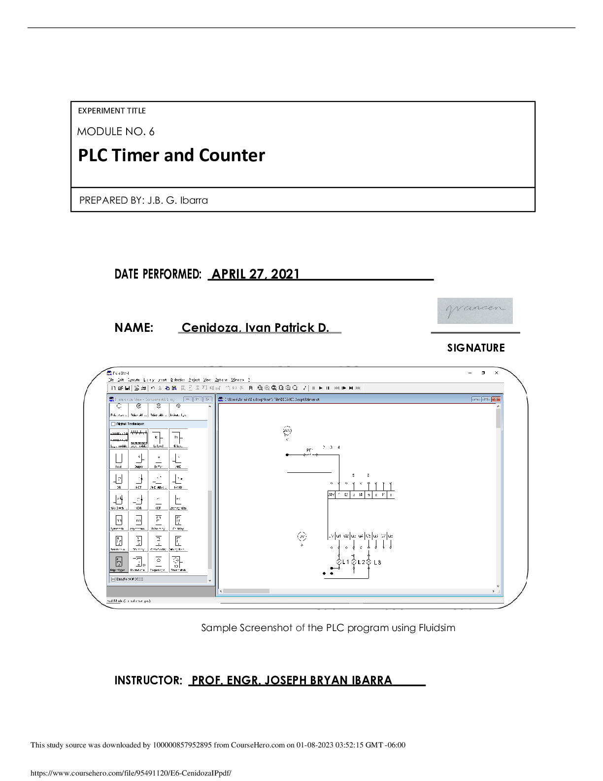
PART 1 : Timer Simulation Given a sequence, design the Ladder diagram and Function Block Diagram: 1.1 a. Lamp 1 turns ON once Start is pressed. b. After 2 seconds Lamp 2 turns ON. c. After 2 seco... nds Lamp 3 turns ON. d. And after another 2 seconds, all lamps will turn OFF. Pressing Start again will repeat the sequence. 4.1.1 Identify the I/O devices then assign addresses for each device. Address I/O Device Description I0.00 PB1 N.C. Momentary Switch O0.00 L1 Indicator Light O0.01 L2 Indicator Light O0.02 L3 Indicator Light 4.1.2 Write the PLC Ladder Program and Function Block diagram: Function Block Diagram: PLC Ladder Program: PART 2: Counter Simulation 1.2 In a brewery plant, a. A momentary, N.O. contact pushbutton is used to select which kind of beer to produce. b. First ON selects Beer_1; Second ON selects Beer_2; Third ON selects Beer_3. c. Fourth ON shall reset selection (all outputs are reset). d. Cycle continues depending on number of Ons on the pushbutton 4.2.1 Identify the I/O devices then assign addresses for each device. Address I/O Device Description I0.00 PB1 N.O. Momentary Switch O0.00 Beer_1 Indicator Light O0.04 Beer_2 Indicator Light O0.07 Beer_3 Indicator Light 4.2.2 Write the PLC Ladder Program and Function Block diagram: [Show More]
Last updated: 1 year ago
Preview 1 out of 6 pages
Reviews( 0 )
Document information
Connected school, study & course
About the document
Uploaded On
Jan 12, 2023
Number of pages
6
Written in

Additional information
This document has been written for:
Uploaded
Jan 12, 2023
Downloads
0
Views
71
.png)
-2.png)
-2.png)


.png)


.png)